1. General and localized lighting lines in offices, parking lots, and mechanical rooms
2. Exhibition halls, production (assembly, inspection) lines, and temporary buildings for lighting or power outlet installation
3. Wiring for lighting, ceiling installations, small power distribution, and communication cabling
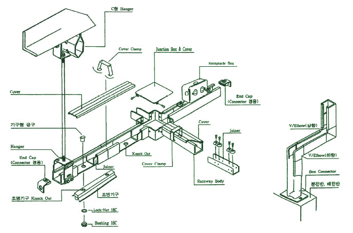
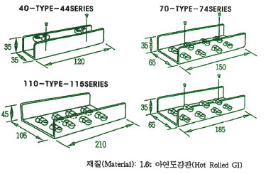
Raceway Body
Knockout holes for equipment installation are placed at 200mm intervals on the bottom surface. For special requirements regarding length, surface treatment, or width, please consult with our company.
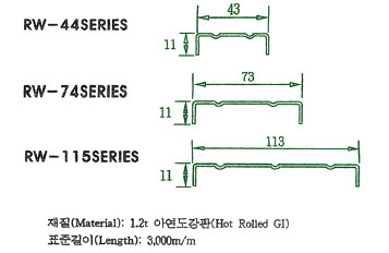
Cover
To protect the cables installed within the raceway, the cover is designed as an out-type structure for easy assembly. Secure the cover to the body using a cover clamp.
Connector (Joiner)
A joining bracket for connecting raceway bodies, designed with an internal connection method to enhance the system's appearance. To install, insert half the length of the joiner into each end of the raceway body, then tighten the pre-assembled bolts. This secures the joiner side within the body’s flanges, ensuring a safe and stable connection.
Equipment Steel Fitting
Used for installing fluorescent lights along the raceway line. To install:
1. Knock out the pre-punched hole at the bottom of the raceway body.
2. Pass the fitting’s connector through both the raceway bottom hole and the fluorescent light hole.
3. Secure the fixture using a knock nut and bushing.
This fitting also functions as a protective conduit, shielding the wiring when connecting fluorescent lighting to the raceway system.
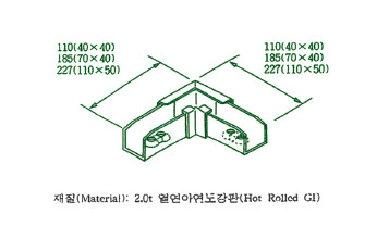
Horizontal Elbow (Out Type)
This fitting is used when the raceway line transitions vertically downward at a 90-degree angle. Secure the connection simply by tightening the pre-assembled bolts.
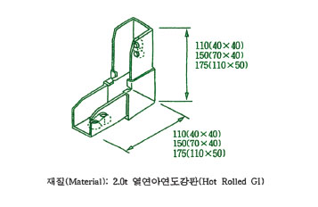
Vertical Elbow (In Type)
This fitting is used when the raceway line transitions vertically upward at a 90-degree angle. To connect it to the raceway body, simply tighten the pre-assembled bolts.
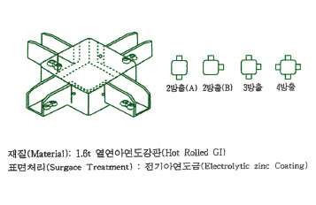
Junction Outlet (1, 2, 3, 4-Way Outlet)
This fitting is designed for horizontal branching of the raceway line in L-shaped, T-shaped, or cross-shaped (+) configurations. To secure it to the body, tighten the pre-assembled bolts.
Box Connector
This fitting is used when the raceway line is connected to a distribution panel or information and communication panel. If the raceway line is extended to a pillar or wall, the box connector should be securely fixed to the wall before connecting the raceway line. This prevents movement and ensures stability.
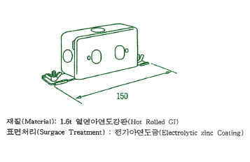
Power Outlet Box
Designed for installing power outlets, telephone outlets, and data communication outlets at various points along the raceway line. The box dimensions follow standard switch box specifications.
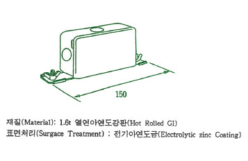
Switch Box
Used for wire splicing, branching, and external connections, as well as for future outlet installations. The box dimensions follow standard switch box specifications.
Cover Clip
Used for securing the new-type raceway cover in place.
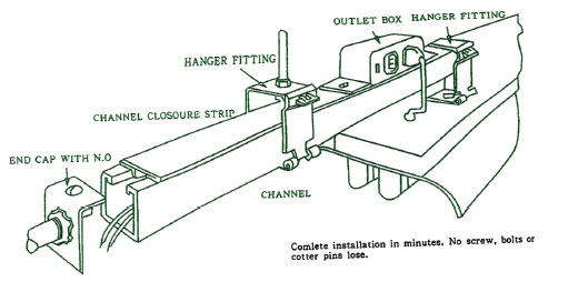
End Cap
Installed at the end of the raceway body, the end cap attaches by hooking its wing section onto the bent edge of the body’s end. It is then firmly secured by tightening the butterfly nut on top.
Additionally, the side of the end cap features knockout holes for direct conduit connections:
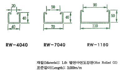
• 70×40mm, 110×50mm series: Compatible with 22mm conduits
• 40×40mm series: Compatible with 16mm conduits
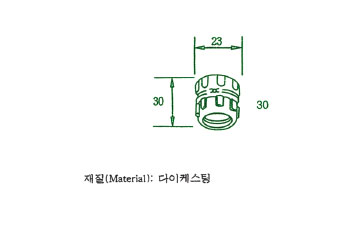
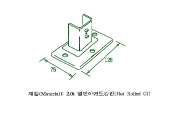
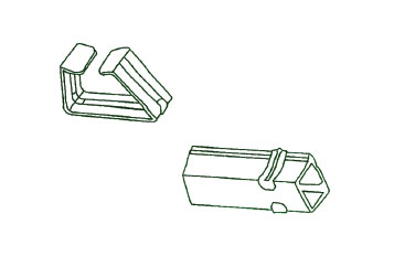
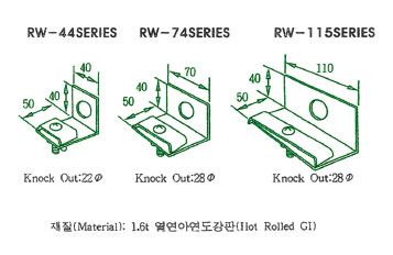
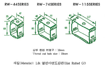
"A" Hanger
A fitting used to support the raceway line by suspending it from a threaded rod (anchor bolt) attached to the ceiling or H-beam. The recommended rod and nut sizes are 9mm and 12mm.
The hanger features a side-open mechanism and is specially designed with an interlocking structure that prevents accidental opening unless force is applied from both the top and side simultaneously.